 Language

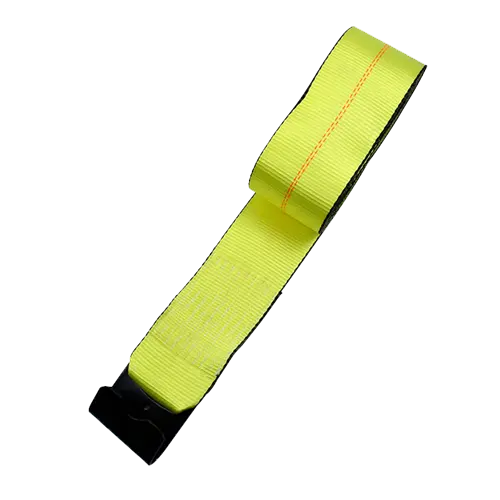
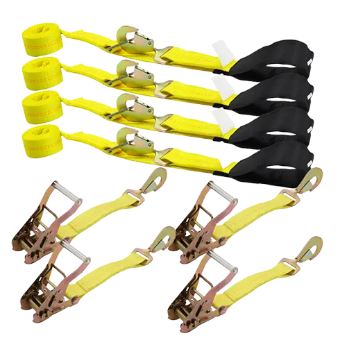
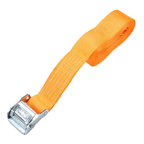

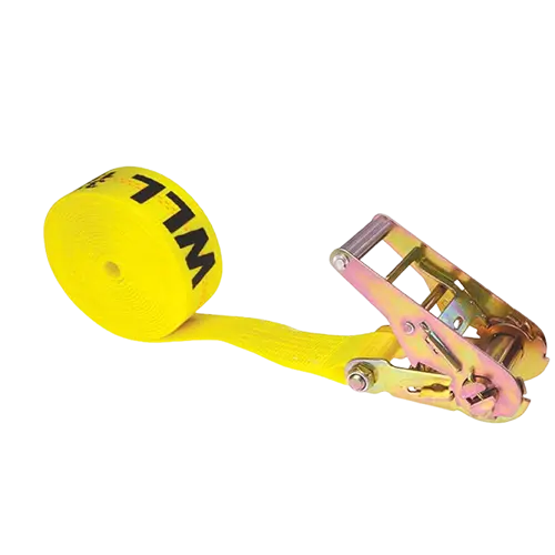
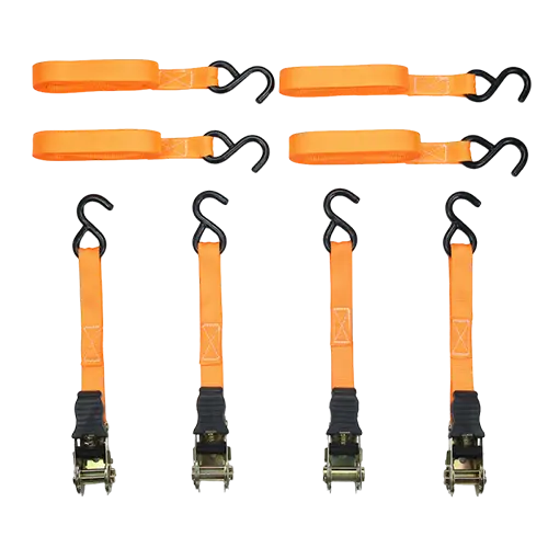
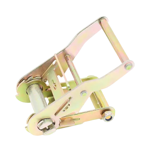
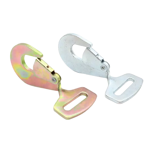
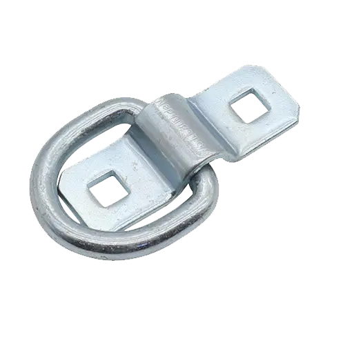
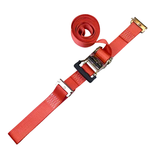
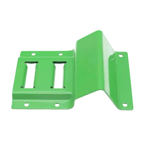
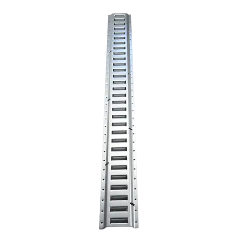




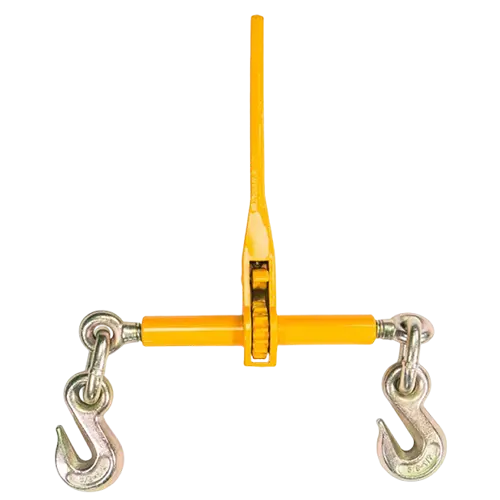
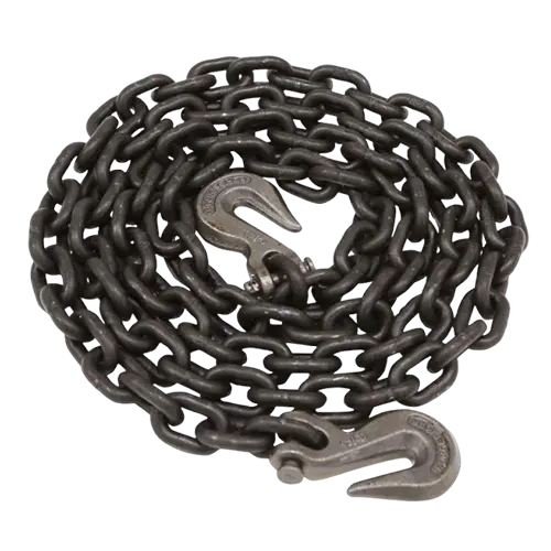






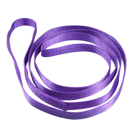


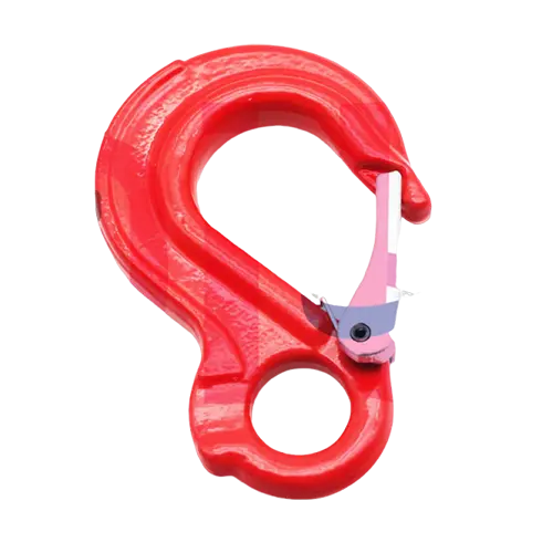


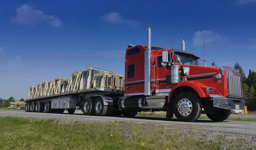
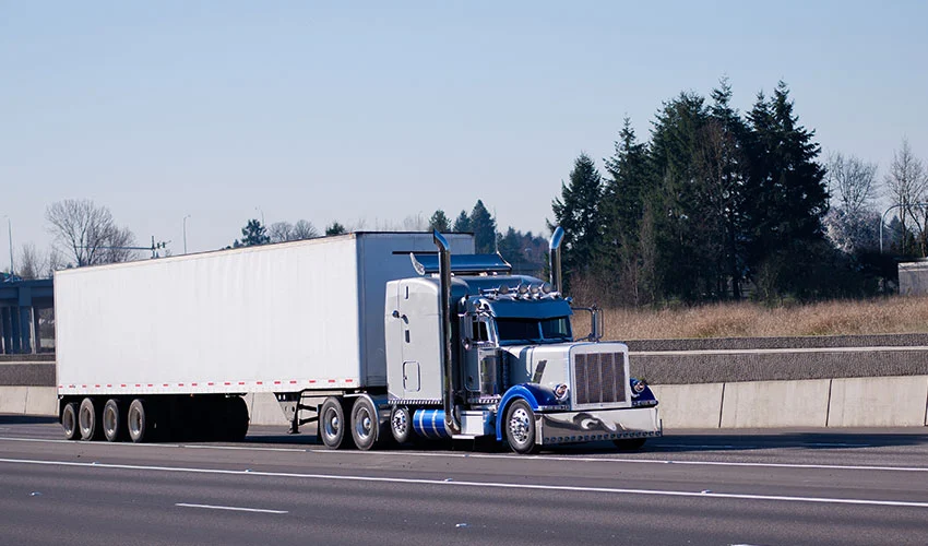
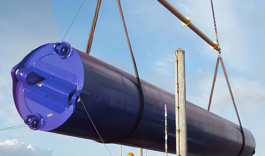
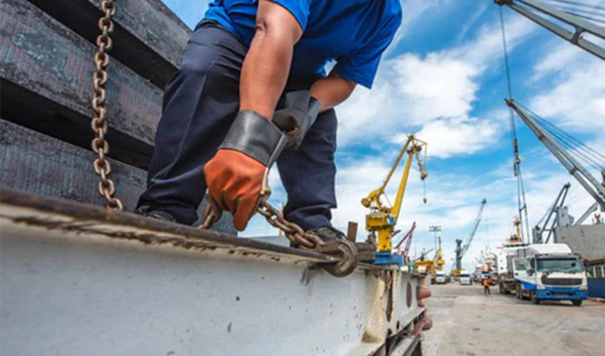
Install E-track around the cargo you need to restrain and the structure available to support it. Confirm the mounting arrangement, dry-fit the rails and fittings, then drill and fasten according to the applicable product and trailer instructions.
An E-track trailer is a trailer fitted with slotted rails that accept compatible cargo-control fittings. The adjustable connection positions are useful only when the rail installation, strap route and operating space work together.
Before buying hardware: identify the supporting members, check behind the mounting surface and draw the rail runs. A familiar bolt size or a layout copied from another trailer is not enough to specify the installation.
Before installing E-track: measure the trailer and locate its supports
Record the cargo footprint and loading route
Start with the largest cargo envelope you expect to carry, its permitted attachment points and the space needed to load it. Mark the door opening, ramp movement, wheel wells, cabinets and the route used by wheels or handling equipment. Keep the trailer's loading requirements in view; a symmetrical rail layout is not a reason to put cargo in the wrong position.
Measure where the fittings must be accessible after loading, not just where an empty trailer has room for a rail. A pallet, cabinet or wheel can block a connection that looked convenient during installation.
Identify wall studs, floor crossmembers and hidden services
Confirm the supporting members separately for the walls and floor. A wall-stud position does not establish the location of a floor crossmember. Distinguish the visible liner or floor panel from the structure behind it, using the trailer manufacturer's drawings and verifiable access where available.
Check both sides of each proposed drilling area for wiring, pipes and other critical components. Record whether there is room to position backing hardware and operate the required tools. If you cannot establish what a fastener will engage or what lies behind it, resolve that before drilling.
For a mounting review, I would ask for marked support locations and photographs of accessible backing areas before discussing screw diameter. Those details define the connection being considered; an interior photograph alone may show only the liner.
| Record | Include | Decision it supports |
|---|---|---|
| Cargo and access | Footprint, height, permitted attachment areas and loading route. | Where fittings must remain reachable. |
| Structure | Verified studs or crossmembers and the mounting-surface construction. | Which positions can be assessed for fastening. |
| Backside clearance | Backing location, tool access and nearby services. | Whether the proposed assembly can be installed and inspected. |
| Rail runs | Ends, joints, obstructions and connection access. | Section lengths and the need to revise the layout. |
Swipe horizontally to see all columns.
E-track trailer layout ideas for enclosed trailers
Separate rail type, mounting surface and pull direction
Record horizontal or vertical rail type, wall or floor mounting, and the intended fitting pull direction as separate fields. A type name does not, by itself, approve every mounting surface or direction. Compare the actual profile, slot arrangement and installation information for the selected product.

Measure usable runs, not just total rail length
Place rail ends and joints on the drawing before counting sections. Check how the mounting holes relate to the verified supports and how the end areas will be attached.
Several short sections do not automatically act as one continuous structural member. A cutting plan also needs to account for cut loss, permitted end treatment and the mounting arrangement of each resulting section.
If a joint or end hole does not suit the support layout, ask for the permitted solution. Do not improvise an overlap or add holes to the trailer structure to make the drawing fit.
The following E-track layout ideas are planning concepts for different uses. They show where to investigate rail placement, not approved dimensions, strap routes or load capacities.
Layout idea 1: wall rails for changing cargo sizes
For general cargo with changing dimensions, wall rails can provide connection positions along a load area. Select the row location from the actual restraint route, available supports and fitting access. Check tall and low cargo separately rather than choosing one installation height from an example photograph.
Layout idea 2: floor rails beside an equipment-loading route
For equipment that needs connections near the floor, investigate rail runs alongside the loading position. Check crossmembers and underside access, then test the clearance with the equipment envelope marked out. For wheeled loads, choose the actual chock, tire or vehicle attachment arrangement from its applicable instructions; wheel spacing alone does not determine rail spacing.
Layout idea 3: a combined wall-and-floor arrangement
A mixed-use trailer may benefit from both locations, but each additional run brings its own mounting and access checks. Keep rails, fittings and stored accessories clear of doors and handling paths. Plan for the cargo arrangement that is hardest to reach, not just the easiest one to draw.
Swipe horizontally to inspect each layout.
Dry-fit the fittings and tensioner as well as the rail
Hold the proposed rail sections in place and check a representative fitting at the intended connection positions. Leave room to operate its keeper and to open and close the tensioner. A rail can fit neatly against a cabinet while leaving too little room to connect a strap.
For example, our red 2-inch by 12-foot E-track ratchet strap lists a 4 ft fixed end. Check where that fixed end places the ratchet in the planned route; overall strap length alone does not establish whether the handle will be accessible.

E-track mounting hardware and backing plates: what to check
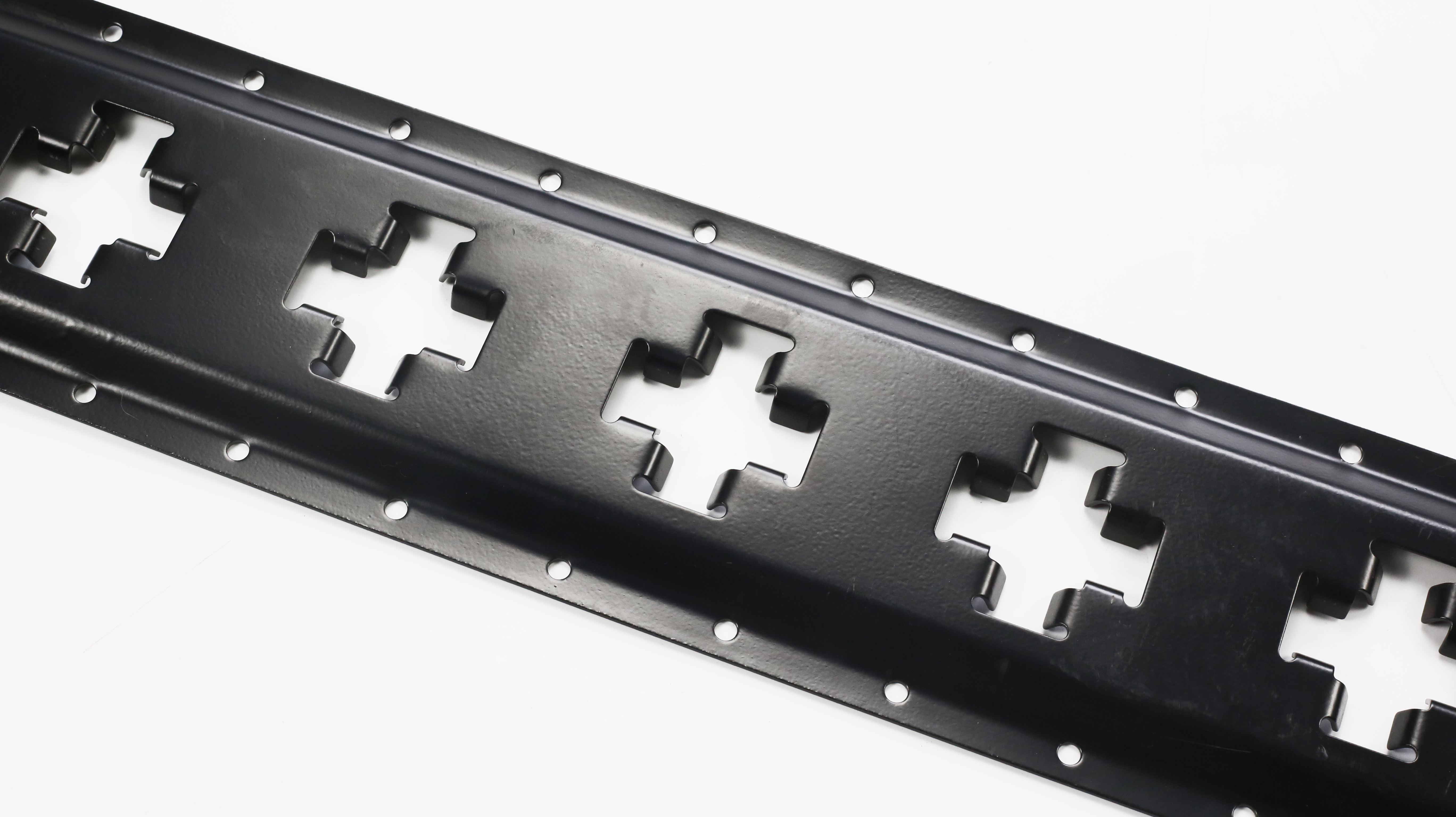
For E-track installed on a wood trailer floor, I would verify the mounting structure before selecting fasteners. Force Rigging's horizontal rail specification lists galvanized steel, a 5 ft length and a 5¼ in width. Those dimensions identify the product; they do not establish its installed working load limit.
Read the complete connection, not just the fastener size
If screws engage only inadequately supported flooring, potential failure modes include fastener withdrawal and local panel damage. A specified through-bolted arrangement with backing still needs checks for wood bearing, fastener strength and support adequacy. Wood connection performance depends on material properties, joint geometry and moisture conditions, not simply bolt diameter. The USDA Wood Handbook, Chapter 8 explains these wood-fastening considerations.
Keep the fitting slots separate from the mounting holes. The larger slots receive cargo-control fittings; the smaller mounting openings serve the specified fastening arrangement. Counting slots does not tell you how many screws to install.

Confirm the fastening arrangement before drilling
Compare through-bolts, specified screws or kit fasteners against the actual substrate and support. Record the required diameter, length, grade, hole details, fastening positions and tightening method from the applicable installation information.
If the proposed hardware does not match that information, settle the difference first. A larger fastener or a greater number of fasteners is not a substitute for an assessed connection.
| Condition | Information to obtain | Do not infer |
|---|---|---|
| Wood floor or liner | Material, thickness, condition, support and the specified engagement or clamping arrangement. | That a familiar screw is suitable for every wood panel. |
| Through-bolted mounting | Complete material stack, fasteners, backing, access and tightening requirements. | That backside access alone establishes a load rating. |
| Thin metal or concealed framing | Verified structure and product- or vehicle-specific fastening information. | That a fastener suited to thick steel is also suitable for thin aluminum. |
| A revised hole or joint position | Permission for the change and the revised end/support arrangement. | That relocating a hole preserves the original installation conditions. |
Swipe horizontally to see all columns.
Check the backing plate and supporting material together
For a fixed force, average bearing pressure follows p = F/A: doubling the effective bearing area halves average pressure, assuming the larger area actually participates in load transfer. It does not double connection capacity or predict service life. A backing plate must work with the fasteners, supporting material and specified arrangement, rather than simply cover a larger visible area.
The same distinction matters when comparing cost. Lifecycle comparisons should include only configurations that already satisfy the securement requirements. As an illustrative calculation, a compliant installation costing 50% more would need more than 1.5 times the service life to reduce annualized installation cost, assuming equivalent duty and equal maintenance costs and excluding financing and downtime. That ratio is a break-even condition, not a predicted durability improvement.
My recommendation is to compare complete, documented mounting arrangements before comparing hardware prices. Extra expenditure has no engineering value if it leaves the support, permitted loading or installation requirements unresolved.
Swipe horizontally to follow the complete path.
Build the installation list from the drawing
List rail sections by location, then add the specified fasteners, backing and protective parts. Keep cargo fittings, straps and storage accessories on separate lines so their functions and ratings remain clear. A kit title does not confirm that every item needed for your trailer is included.
Prepare measuring and marking tools, the specified drilling equipment, suitable access equipment and the required tightening tools. Check material compatibility, exposed-hole protection and sealing requirements against the installation documents. Do not select a coating or isolation material solely because it worked on a different vehicle.
How to install E-track on a wood trailer floor
Use this sequence with a mounting arrangement specified for the selected rail and trailer construction. Obtain that arrangement before starting; the steps below do not assign a universal bolt size, hole spacing or floor load rating.
-
Check the floor construction and underside access
Confirm the floor material, thickness, condition and crossmember locations. Inspect the proposed backside positions for services, obstructions and tool access. Make sure the required backing and fasteners can be installed and later inspected.
-
Mark the rail runs and specified fixing points
Dry-fit the sections, mark their ends and joints, and compare the proposed fixing points with the verified supports. Check the cargo envelope, loading route and fitting access. Resolve a mismatch before marking permanent holes.
-
Prepare the mounting locations as instructed
Verify safe drilling clearance on both sides. Follow the specified hole type, diameter and depth for the actual fastener and material; do not assume every screw requires the same pilot-hole treatment. Remove debris and carry out the required edge protection or sealing.
-
Fit the rail, backing and specified fasteners
Assemble the components in their required positions and check their contact with the mounting surfaces. Follow the stated tightening method and torque where specified. If a surface crushes, a hole strips or a rail will not seat correctly, stop and resolve the cause instead of applying more torque.
-
Check operation and record the installation
Verify fitting engagement and release according to its instructions, then check the strap route and tensioner clearance. Record the installed components, support positions and accessible backing details. Complete the configuration and rating checks before loading.
How to mount E-track on trailer walls
Wall mounting requires its own structural and clearance review. A fixing detail selected for a wood floor does not automatically apply to a thin wall or concealed frame.
-
Confirm the wall construction and backing access
Locate the framing and establish what the fasteners will engage. Identify liner thickness, trim, cavities and hidden services. Use the applicable trailer and rail information to confirm the proposed mounting arrangement.
-
Choose the row position from the cargo route
Mark the intended rail position and dry-fit the cargo connection. Check the pull direction allowed for the components, plus cabinet, door and wheel-well clearance. Confirm that the fitting keeper and tensioner remain accessible after loading.
-
Align rail sections with the specified supports
Check mounting holes, section ends and joints against the support arrangement. Resolve raised trim or uneven surfaces using the permitted mounting detail. Do not force the rail flat, invent a spacer arrangement or add structural holes without the required approval.
-
Prepare and fasten the wall-mounted assembly
Follow the specified drilling, protection and fastening sequence for the actual materials. Install the required backing and hardware, and use the stated tightening method. Keep fitting slots unobstructed and distinguish them from the fastening holes.
-
Verify access, engagement and configuration
Check the fitting's lock and release operation and the tensioner's working space. Confirm the installed parts against the layout and mounting documents. Record any change and resolve its effect on the applicable rating before the installation enters service.
Check the installation and resolve common problems
Separate three questions: does the connection operate correctly, does the installation match its specified arrangement, and is the rating basis applicable to the intended use? Pulling on the rail by hand can reveal obvious movement; it does not establish a working load limit.
For U.S. commercial transport applications covered by the rules, 49 CFR 393.104 addresses securement-device condition, supporting structures and anchor points. An installation check must look beyond the strap to the structure carrying its load.
| Observation | Check | Next action |
|---|---|---|
| An end hole misses a support | Section length, joint position and permitted end fastening. | Confirm the revised layout rather than improvising an overlap. |
| A fitting cannot seat or release | Fitting identity, slot condition, debris and surrounding clearance. | Resolve interference or replace damaged parts as instructed; do not bend the keeper or slot to make it fit. |
| The surface dimples or the rail lifts | Contact surfaces, supporting material and fastening arrangement. | Stop and assess the connection; more torque is not a corrective design. |
| Backing fits but tools do not | Assembly sequence, underside space and future inspection access. | Resolve access before committing to the layout. |
| A new cargo route changes the pull | Allowed connection direction and simultaneous loading. | Recheck the arrangement and applicable ratings before use. |
Swipe horizontally to see the checks and next actions.
Keep component ratings and installation capacity separate
Under 49 CFR 393.108(a), for covered applications, tiedown WLL is limited by its lowest-rated component or the lower anchor-point rating. Do not use a strap label as proof of the rail mounting's capacity, or add rail ratings without checking shared supports and the applicable loading case.
For the strap specification itself, our ratchet strap buyer's guide explains the fields to compare. Installation capacity, aggregate tiedown WLL and vehicle payload remain different checks.
Keep a configuration record that can be checked later
I would keep the section layout, component identities and photographs of concealed mounting details together. A later change in cargo, strap direction or fittings is much easier to assess when the original arrangement can be identified.
- Identify each rail run, its joints and the supporting members used.
- Record the specified fasteners, backing and installation requirements.
- Keep photographs of accessible backside details before they are covered.
- Record fitting operation and clearance checks separately from the rating basis.
- Recheck the arrangement after damage, movement or a configuration change.
Do not improvise an overload test to establish capacity. Where testing is required, use a defined procedure and competent assessment for the actual configuration.
E-track installation FAQs
How high should E-track be installed on trailer walls?
Choose the row position from the cargo restraint route, verified supports and fitting access. Check the permitted loading direction and the tensioner's operating space. A height used on another trailer is not a universal installation requirement.
How far apart should floor-mounted E-track rails be?
Determine spacing from the cargo envelope, permitted attachment arrangement, available supports and loading route. Include clearance for fittings, wheel wells and handling equipment. Use the actual vehicle or equipment securement instructions where applicable, rather than a fixed spacing for every load.
Does every mounting hole need a fastener?
Use the fastening positions required for the specified rail and mounting arrangement. Do not decide by counting fitting slots or copying a hole pattern from another installation. If the required positions do not suit the trailer structure, resolve the layout or mounting detail before drilling.
Can I recess E-track into a trailer floor?
Only use a rail and installation arrangement suitable for that configuration. Confirm any permitted floor modifications, supporting structure, fitting clearance and protection requirements. Do not rout a channel or cut a structural member simply to make a surface-mounted rail sit flush.
Can E-track sections be cut or joined?
Check the selected product's instructions and the required end and joint mounting details first. Account for cut loss, edge protection and fastening access. A joint does not automatically transfer load like an uninterrupted rail, and an overlap is not an approved connection unless the applicable design permits it.
Can I use regular ratchet straps with E-track?
Use compatible E-fittings or a suitable rated adapter that accepts the strap's end hardware. Ordinary S-hooks, J-hooks and flat hooks do not become locking E-fittings by fitting through an opening. Check the geometry, engagement and ratings of the complete connection.
Send a mounting brief, not just a trailer length
Prepare the cargo envelope, marked support locations, rail runs and proposed fitting configuration. Include mounting-surface details and photographs of accessible supports when discussing Force Rigging E-track components.
Contact Force Rigging at joe@forcerigging.com or +86-18650363763. Use the applicable product and trailer installation information to confirm the final mounting arrangement.
Discuss your E-track configuration